Flexing with Flex Sensor

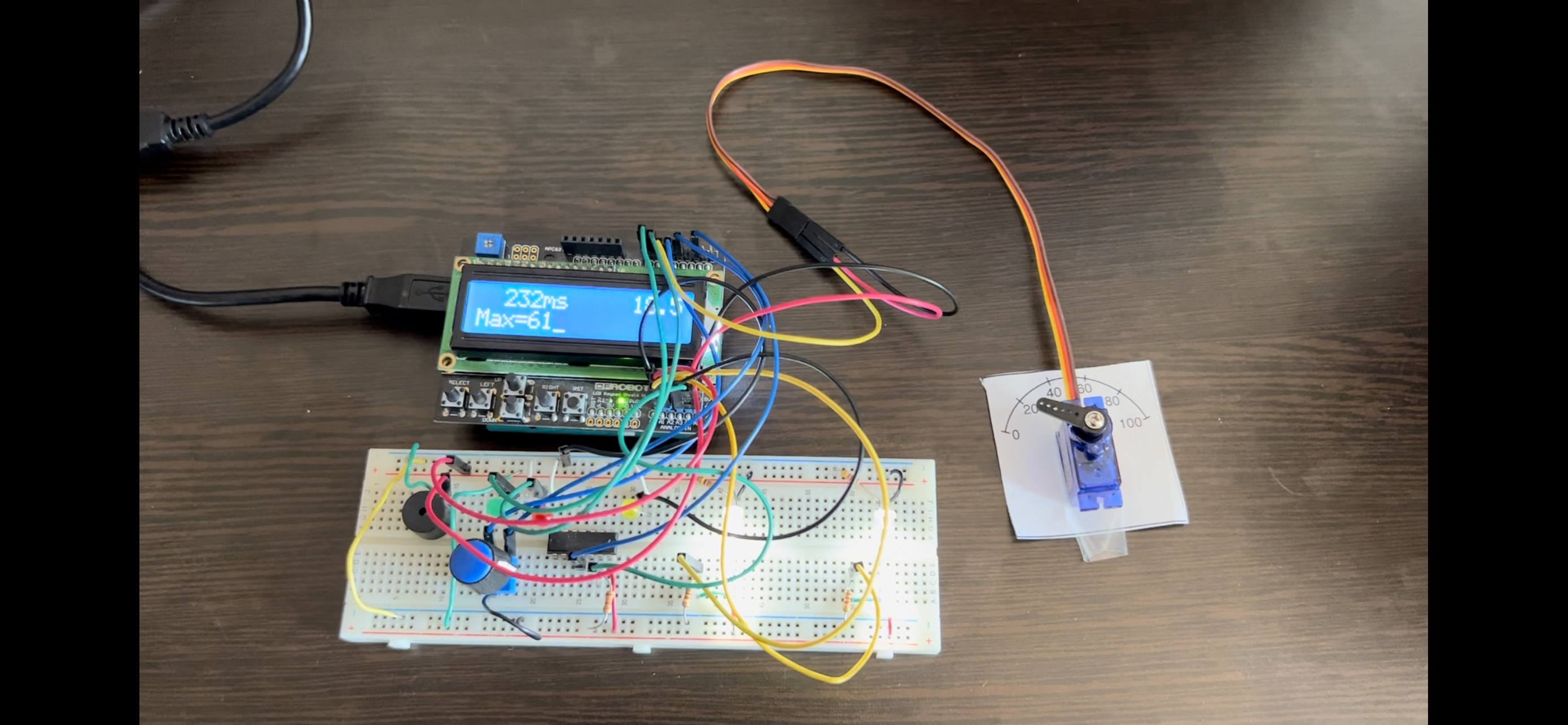
Today I was able to experiment with LED Lightbulbs with Flex sensors. I learned that Flex sensors are resistors. In this experiment, the output of the flex sensor is connected to an analog pin that send analog values to the uno board. The analog values that range from 0-1023 are then mapped to the PWM(Pulse width modulation) values that range from 0-225. After mapping out the analog values, the board then can utilize PWM waves to control the brightness that is given off by the LED light bulb. The brightness of the bulb depends on the duty cycle of PWM waves. By altering how long the power is on for and when the power is off during a cycle over many cycles, we are able to witness a change in the average voltage that a device is experiencing. For instance, a 50% duty cycle experiences a 50% power on as well as a 50% power off. As a result, the receiving device is receiving 50% less voltage on average compared to when the duty cycle sends for power to be on at all time. Knowing how PWM waves alter the voltage by deciding when to send the jolt of power, we are able to utilize the flex sensors analog values to control the brightness of the bulb.


Comments